![[LinuxFocus Image]](../../common/images/border-short.jpg)
| News Archives Map |
|
|
|
|
![[Photo of the Author]](../../common/images/Antonio-C.gif)
by Antonio Castro <acastro(at)ctv.es> About the author: Computer Science is my profession and also part of my free time. I like to share my hobby, as everyone probably does. I admit it! I am one of those strange characters who dislikes windoze. Translated to English by: Miguel A Sepulveda <sepulveda(at)linuxfocus.org> Content: |
Povray II: Basic Notions![[Illustration]](../../common/images/illustration11.gif)
Abstract:
This is the second article on a series about Povray. This time we
review some general concepts and start describing the basic elements of
the language
|
The animations were built in low resolution with only 15 frames in JPEG format. Limiting the resolution and size of the animation we hope to avoid using too much hard disk and making this article slow to download. Nevertheless, as always the sources for these images will also be provided and the readers have access to the tool 'pov' (discussed in the previous issue) that will render the images at any desired resolution, or allow readers to modify and experiment with the images.
If the reader has not installed Povray yet on their system, please follow the directions in the previous article in this series where we gave sufficient information on the location of the sources, installation and configuration of POVRAY.
In the previous article we mentioned briefly the notion of ray tracing. Let us now explore this issue in more detail.
Rendering is the most complete technique to achieve a synthetic image. It tries to emulate in the most realistic but inexpensive manner the behavior of light and its visual effects on objects.
In our previous article we mentioned that the renderer computes the number of light rays, but interestingly enough the light source under this model behaves not as a source but as a sink, while the camera acts as the source of rays. There is a reason for this inversion of roles, if rays departed from the light source then there would be a great waste of computational time because out of all the rays that leave the light source only a very small number eventually reaches the camera. Following the points the image from the camera we are reducing the number of rays to only those which are relevant for the image. Each of the points in the image corresponds to a point in the hypothetical photosensitive film of our virtual camera. Every point is then processed independently. We have configured Povray to build the image and then visualize it with an external viewer. Had we configured Povray for SVGA then we could see that it is possible to view the image as it is being computed. This is done pixel by pixel, from left to right, top to bottom on the screen. The order is not coincidental. The most common output format for Povray is TGA 24 bits, which is constructed precisely in that order.
If anyone gets interested on configuring Povray for SVGA (I have not done it myself) the first thing that you will learn is that the speed of rendering depends on the region of the image, complex regions take longer than simpler regions. Zones with many objects take longer time to process than zones with one or none. For every impact of the rays into the objects the renderer calculates the effect on the light by looking at the position and color of the light source, its relative position with respect to the object's surface, as well as the texture of the object and other physical characteristics. The result of this calculation is specified in three RGB values that define the color and intensity of the point in the image.
A brief tour
The TGA 24bits format occupies a lot of space but is trivial to generate and easy to process.
Each pixel is given by three numbers of 8 bits that codify the RGB
packet
8bits *3 = 24 bits; 2^24 = 16777216 (16 million colors)
|
This information should be sufficient to process some images and achieve a few interesting effects. If the reader has some experience with programming we propose the following exercises:
1) Brighten/Darken an image (white pixels are 255,255,255 and black
pixels 0,0,0
2) Superimpose an image with a black background on top of another one
using black as a transparent value
3) Blend two images by averaging color values
5) Enhance/reduce a given colour
6) Obtain the color histogram of an image (list of colors and their
frequency)
All these operations can be accomplished using auxiliary programs often available on the web. Nevertheless, on some occasions we may need to apply a non trivial transformation to the image and this TGA format of 24 bits is very manageable.
End of Detour
The rays depart from a point in the film of the virtual camera but to calculate the resulting colour each ray determines whether it intercepts any of the objects in the scene. If it does the ray-tracing algorithm continues analyzing the characteristics of the object in the area reached by the ray. Then there is a very effective optimization technique for designing complex objects. It consists of defining a new invisible object that contains the first complex object. Generally the most common used container is an sphere, but boxes are also popular. The main goal here is to use the container to force the ray-tracer to approximate the complex object by using the container instead, arriving rays bounce off the invisible spherical container. This removes a great deal of the computational process. The primitive used is "bounce_by" and it is commented next to illustrate how well the ray-tracer works. We will see an example later on in the article when we treat complex figures.
As an illustration of the issues explored so far let us review an image created using several techniques and discuss them one by one
This scene is titled the "7 Errors"
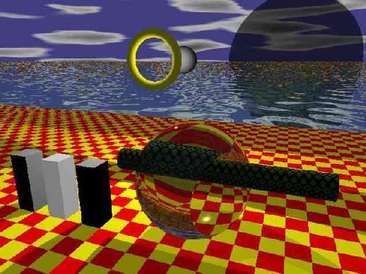
Please notice that some of the features of the scene are odd:
At this moment we can not really explain the details of the numerous techniques used. Our point with this example is to show the reader that ray tracers attempt to imitate natural phenomena but they are not always totally compliant with natural laws of physics because there is a high price to pay in terms of processing time for a greater degree of reality. Some techniques are mostly good to fix defects produced by others. What is most important is to find a balance between final result and processing time.
This series about Povray can not go beyond a superficial excursion of its possibilities. The Povray language is too extensive to be treated in depth in the series. For this reason at this moment we can only make a few remarks on the most important features of the language.
Often Povray permits use of a number of grammatical forms to accomplish the same result. This is due in part to the genesis of Povray, the actual syntax of Povray has profoundly changed from version to version. The current syntax is very much improved and perhaps will not suffer so many changes in the future. For compatibility reasons old syntax features are preserved in newer versions in its original or slightly modified form. An example of flexibility in the syntax are the rotations that we will examine shortly.
There is a compilation option that allows to process the input source file using previous versions of Povray.
For example:
|
Amazingly this allows the developer to mix source code written in Povray 1.0, 2.0 or 3.0
There is already a very good manual on Povray so please refer to it. Here we will save time by pointing to most important features.
Comments, Declarations, Include files
Comments are written following the C++ style.
Example:
|
The elements starting with '#' are known as Language Directives. The most commonly used directives are '#declare' and '#include'.
|
Example:
|
The statement '#declare' can be used to store a great variety of elements: a rotation, texture, color, object, numerical values, ...
Another crucial element is include statements that allows you to include source file code fragments previously saved in other files.
By default the include directive searches the local directory for the file. If the file is not found it then passes to search the Library_Path.
Library_Path=${POVRAY}/include // For the include files of
Povray
Library_Path=${HOMEPOV}/include // For the user include files
This is what I have implemented in the new version of the script 'pov' to generate an appropriate initialization file. We will come back to this.
There is a collection of include files one has to be familiar with to get the maximum output from Povray. It is a library of resources that can be included in our code and also customized to the developers taste.
|
Povray also has directives that implement loops and conditional statements. The first versions of Povray lacked directives for loops or conditionals, moreover the description of elements in the scene could appear in any order and as result the developer had to take a big mental departure from traditional programming languages. The order of declaration of elements in the scene is still irrelevant but the loops can save the developer from writing multitude of similar lines and the conditional lines let us for example define a scene according to the value of the 'clock' used in animations. When we discuss composite images in the next article we will give an example of conditional statements.
There are many more language directives (beginning with '#') but we insist that the two presented here (i.e '#declare' and '#include') are by far the most often used.
I will skip discussing language features that are very similar to other programming languages like constants of various types, logical operators, relation operators, operators for vectors, predefined functions, etc..
It is convenient to use at least one upper case character for identifiers labels in order to distinguish them from the reserved words of the language.
Dealing with this issue so early on deserves a short explanation
It is often said that an image is worth a thousand words, and this is especially true when we try to explain the functionality of a ray tracer. We will try to illustrate abundantly each concept, otherwise the reader would be forced to write code to test the explanations using his own examples in order to follow the article. This is one of the main reason for including so many images in the Povray series. Our hope is that consulting the images included might be sufficient to remind the reader of the concept studied avoiding that you have to go through the text once more. Sometimes an image is not sufficient and instead we require a sequence of them to see small differences between images and special effects. This is why we see it justified to discuss animations at this moment.
Povray limits itself to generate a sequence of images and save them to the disk one at a time. For the moment we are only interested on a very simple method. The ray tracer will be launched several times passing each time a number that selects the image in the sequence to be produced. In order to re-launch multiple times Povray there are some nice options that can be added to the *.ini file specially thought for generating animations:
|
Since in our previous article we proposed a simple program to generate *.ini files thus making the use of Povray simple and convenient let us proceed to update it in order the allow the generation of animations.
The new script has an additional include directory that can be shared among several projects, '$HOME/dat/pov/include'. This would be the ideal location to place user libraries.
|
From time to time we will use utilities external to Povray. For example to visualize animations we will use the utilities "animate" and "convert" from imagemagick.
Once I asked Enrique Zanardi, the maintainer of the Povray package for Debian whether there was a modeler for Povray. He wrote:
I have used ScEd (also available in Debian). Once you get used to it, is very easy. It can be compiled using a Scheme interpreter so that users can define their own "tokens", no matter how complex. People also recommend Ac3D but I believe it is not free.
There is another method for generating animations. This methods was very popular with the first versions of Povray but it is still a valid option. It consists of an external program that generates a loop that launches Povray several times. During each iteration of the loop the program generates a file to be included through a '#include' statement in the main source, each of these files contains information about the current time.
Here is a C code fragment that demonstrates the second method:
-------------8<------------------------------------
for(Frame=1; Frame < UltimoFrame; Frame++){
   fi=fopen("pajaro.inc", "w");
   fprintf(fi, "#declare PosX_pajaro1 = %d\n",
         FuncionPosX_pajaro1(Frame));
   fprintf(fi, "#declare PosY_pajaro1 = %d\n",
         FuncionPosY_pajaro1(Frame));
   fprintf(fi, "#declare AnguloAlas_p1 = %d\n",
         FuncionAngAlas_p1(Frame));
   fclose(fi);
   sprintf(comando,"povray -ipajaro.pov -opajaro%04d.tga",Frame);
   system(comando);
}
-------------8<------------------------------------ |
In the following section we examine an example of animation that illustrates the specification of rotations and translations.
The position of an object is determined by its coordinates <x,y,z >. It is common practice to define objects centered at the origin of coordinates.
Any object can be moved from it initial position to a well defined location <x,y,z > by using a translation. The best way to represent the data of a translation is through vectors. Vectors are very often used in POVRAY. A common shorthand notation for a vector with x, y and z components is <x, y, z> ; if all the components are identical then <24, 24, 24> = <24>. POVRAY predefines three vectors: x=<1,0,0> y=<0,1,0> and z=<0,0,1>. Then 3*y = <0,3,0> and -2*x = <-2,0,0>.
Often it is necessary to work with paper and pencil to plan were to place objects in an scene. It also helps to start from an initial guess and use POVRAY to generate images at low resolution and low quality so that by trial and error we can determine the best location for the objects.
The 3D transformations available in POVRAY are:
rotate <VECTOR>
scale <VECTOR>
translate <VECTOR>
Translational and rotational transformation are very useful for animations as well as for setting up objects in a complex scene
Any object can be moved to a different location by adding a vector which is calculated by subtracting the initial coordinates from the coordinates of the final location. Geometrically this vector of translation can be viewed as an arrow going from the initial location to the final location. Here is an example:
sphere { <2, 2, 2>, 10
pigment { White }
translate <-3> // Remember <-3> = <-3, -3, -3>
}
The result is an sphere of radius 10 centered at <-1,-1,-1>
Objects can be rotated arround axis going through the center of coordinates. This is a common convention to express rotations and because of this objects (that should be represented centered at the origin) are first rotated to the appropriate orientation and then translated to the final location. Notice that the opposite order of operations (first translation and then rotation) would not yield the same result.
A rotation must be defined by specifying a rotation axis and an angle of rotation around that axis. The sense of rotation follows the left-hand rule (take your left hand with the thumb pointing along the positive direction of the axis and then close your fist, the direction of motion of the closing fist shows the direction of rotation).
There are two ways of defining a rotation in POVRAY: "axis * degrees" or " <n,n,n>" that represents three rotations about the X, Y and Z axis. Here are some examples:
rotate x * 45 = rotate <45, 0, 0>
rotate <45, -30, 20> = rotate x*45 rotate y*-30 rotate z*20
rotate 20*z = rotate z*20
rotate y*90 x*90 = rotate <0, 90, 0> rotate <90, 0, 0>
rotate y*90 x*90 != rotate <90, 90, 0>
The last example is not an equality and this is a case that often leads to errors. The order of rotations is very important. When using the notation <n,n,n> rotations are performed in the X, Y and Z order and whenever a different order is necessary one must concatenate several rotation instructions. We will use preferably the notation "axis * degrees". If desired the developer can use angles in radians by using the function "radians". There are many mathematical functions in POVRAY that facilitate the evaluation of mathematical arithmetic.
The size of objects can be modified by using scaling transformations. Three numbers are used to scale the X, Y and Z directions of an object. This allows to increase, decrease and flatten an object.
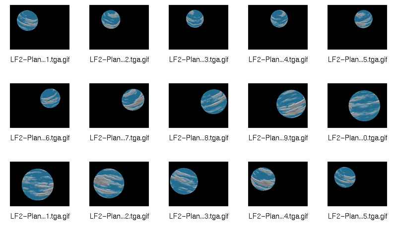
Translation and scaling operations can be performed in any order. However the presence of a single rotation operation is enough to break the commutativity of the operations and thus order becomes very important. Here is a simple example to illustrate the importance of ordering with 3D transformations. It is a blue sphere rotating about is center and an external point. The axis of rotation at the center of the sphere is slightly declining in the horizon.
|
----------------------------------8<------------------------------ #include "colors.inc" #include "textures.inc" //##### To launch animation execute: ###### //# pov PlanetAzul 4 9 1 100 1 360 # //############################### #declare RY1 = clock * 5; #declare RZ1 = 25; #declare T1 = <5 ,0 ,0 >; #declare RY2 = clock; camera { light_source { <-15, 15, 15> color White} sphere { <0, 0, 0> 4 |
To launch the animation we use the new version of 'pov' and execute:
./pov PlanetAzul 4 9 1 100 1 360
This is what the parameters mean:
Next we show a few frames of the animation. It is not good enough for a realistic model of the planet Earth but it is sufficient as a metaphor
Example planetblue.jpg:
Light sources are modeled as point sources in space. The point of light source has no dimensions and is invisible in the sense that a camera focus on it will show nothing. A light source is only perceived by its effects on nearby objects. By the default this point shines light in all directions, although it is possible to define spot lights (light irradiated as a cone). The default color is white and this attribute can also be change as well as the intensity of the light.
A scene may have one or more light sources in order to produce the appropriate lighting and shadows. However increasing the number of light sources means also to increase the amount of CPU used to generate the image.
|
Webpages maintained by the LinuxFocus Editor team
© Antonio Castro, FDL LinuxFocus.org |
Translation information:
|
2002-11-02, generated by lfparser version 2.34