![[LinuxFocus Image]](../../common/images/border-short.jpg)
| News Archives Map |
|
|
|
|
![[Photo of the Author]](../../common/images/Miguel-S.jpg)
by Miguel A Sepulveda <Miguel.Sepulveda(at)disney.com> Content: |
OpenGL Programming: The 3D SceneAbstract:
We explore the bolts and nuts of 3D rendering with OpenGL. The
directives examined in this issue fall into two categories, 3D
geometrical transformations and matrix projection operations.
|
After a long excursion into other issues we finally reach the point of discussing 3D graphics under OpenGL. I will not by lie telling you it is an easy topic because it is not. Any good OpenGL programmer of 3D applications, and in particular, animations, should be quite knowledgeable on Linear algebra, Analytical Geometry, Physics (mechanics) and of course quite a bit of Numerical Analysis.
I will try to make the rest of this series as accessible as possible to everyone. Unfortunately there is no way around having to know about matrices, how planes and surfaces are represented mathematically in 3D space, vectors, polynomial approximations to curves, to mention just a few.
During the last weeks I have debated how to present this more complicated material to a broad audience. Standard books follow a step by step approach, more or less the method I have followed in the previous two articles. I decided not to take this path anymore because it would take too much time (months) to get the reader to the point of writing his/hers own code. So instead I will venture using another method, I decided to call it the "shock treatment". This time I will include in this article a demo of one of my 3D simulations, and then try to explain to you bit by bit what is in that code. Eventually we will explore in more detail all the issues normally treated in standard OpenGL books but I believe by jumping to the end and giving the reader a sample of code with some interesting things it will prompt users to experiment with it and try things, even though I will not tell them this time how everything works exactly. I hope this method works and people find it faster and more direct.
So lets get down to the nuts and bolts. For the past 6 months I have been working at the University of Pittsburgh on an Object Oriented toolkit to support the development of polymer and gel simulations. The project is quite advanced already, the physics is very interesting even to people from computer science because a gel is basically a neural network of polymers and many of the techniques developed for neural networks also apply to gel construction. I have picked a few stripped down objects from the toolkit and packaged it into this simple demo example2.tar.gz. It can be compiled under Linux, any other UNIX environment or windows 95/NT (provided you previously installed GLUT). The demo shows a single polymer (a linear chain of linked monomers) moving while in suspension on solution at some temperature. The dynamics are tantalizing. It looks like a snake on stimulants! It is very lively due to the collisions of solvent molecules. You will not see the solvent, as it is taking care of through the equations of motion of the polymer.
![[model of polymer]](../../common/May1998/ogl1.jpg)
The model used to render the polymer is quite simple; example2 keeps track of the (x, y, z) coordinates of every node (monomer) across the polymer chain. At every frame of the animation we draw a sphere at the coordinates of the monomers and them join them using cylinders that go from monomer to monomer. So there are two elemental 3D primitives, a sphere and a cylinder. As with any molecule, the distance between monomers changes in time, therefore we cannot use "one cylinder" to draw all the links, it must be rescaled according to the current monomer-monomer distance.
Question 1: Say you have two 3D objects, a sphere and a vertical cylinder of height 1. Let us also say that both objects are centered at the origin of the coordinates. If all that you know about the polymer is the sequence of x, y, z coordinates for the nodes how would you scale, rotate and translate replicas of our primitive cylinder to build the polymer links?
For some reason that I do not understand computer scientist decided to switch the conventional meaning of cartesian coordinates: x is horizontal, y is vertical and z goes towards the viewer. Be aware of it because if you come from the math or science background it will confuse you at first.
There is a nice informational banner on the upper part of the animation window that lets you know the current time, the current temperature of the polymer, average temperature of the polymer, temperature of the solution, the friction of the solvent, and the rotation angle of the outside camera. In order to give a fuller view of the polymer from all sides, the camera (your point of view) rotates slowly around the center of gravity of the polymer.
Actually the polymer length I chose for this demo is so short that rotating the camera was not really necessary eventually the polymer will rotate by itself. Go ahead edit the file example2.cxx and modify the definition POLYMERLENGTH anywhere from 2 to 100. The camera rotates because I wanted the reader to realize one apparent problem: Changes of the system of coordinates. The coordinates of the nodes are used by the equations of motion and therefore they are in world coordinates, independent of the particular point of view of the user. These coordinates must be mapped into the 2D x-y coordinates of your computer screen. Every time your point of view changes the formulas to transform the polymer internal coordinates into 2D window coordinates change.
Question 2: How would you solve this problem? Changing the equations of motion from real world coordinates to 2D viewpoint coordinates is out of the question, it would involve too much algebra, be very complicated to implemente and be too prompt to errors
The answer to question 2 is simple. There is only one option, to perform the dynamics and representation of the 3D model (polymer) in world coordinates and then to change the world coordinates to 2D viewport coordinates at the moment of rendering the frame. OpenGL is quite efficient at performing these transformations, they are even supported at the hardware level (those who own OpenGL graphics cards will see the difference). But before describing how OpenGL approaches this problem let us first consider how many coordinate transformations there are from the real world 3D coordinates to the final 2D window coordinates.
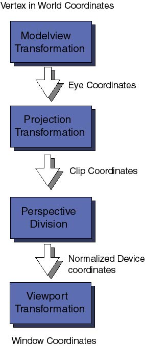
First comes the Modelview coordinate transformations. They map the original world coordinates into eye coordinates, these are 3D coordinates relative to the position of the viewer eye (or camera). It is called Modelview transformation because it really involves many similar though distinct operations. Modeling and Viewing projections , the latter is analogous to the positioning of a photo-camera in a studio looking toward the scene to be photograph; the modeling projection is then similar to the positioning of the objects of interest in front of the camera.
Following the pipeline of transformations, the eye coordinates are passed to the Projection coordinate transformation. The purpose of these transformations will sound a bit esoteric at the moment. After positioning the camera in the viewing direction and setting the objects in the field of view, OpenGL wants to now how much of the field of view should be mapped to the computer window. For example, the camera may be directed towards a very distant mountain, the field of view defines a large volume of space. Computers can only handle finite things, so we have to specify how much of the total field of view should be clipped out. This transformation also takes care of removing hidden surfaces from the viewer. The final coordinates obtained are the Clip coordinates, remember always that it is not sufficient that your 3D objects is in front of the camera but it must be within the clipping planes defining the projection transformation. The various 3D perspectives (conical, orthogonal for example) are defined at this level.
For the moment we will not enter into what a perspective division is, nor what the difference between clip coordinates and normalized device coordinates are. It is not necessary to get into this yet.
The last important coordinate transformation is the Viewport transformation. Here the 3D coordinates that have gone through all sort of 3D transformations are finally map into the 2D area of your computer window.
Coordinate transformations are represented by matrices (two dimensional arrays of numbers). To each of the above transformations there is an associated matrix. They can be specified at any moment of the program before rendering the frame. OpenGL keeps a stack of matrix transformations to be performed on every vertex on the scene. This is a very efficient and powerful technique and we will explore it in future articles. For the moment let us dive into the source code and see how and where some of these transformations were defined. In the example2.cxx file there are the already familiar reshape functions:
void mainReshape(int w, int h){

  // VIEWPORT TRANSFORMATION
   glViewport(0, 0, w, h);

  // PROJECTION TRANSFORMATION
  glMatrixMode(GL_PROJECTION);
  glLoadIdentity();
  glFrustum(wnLEFT, wnRIGHT, wnBOT, wnTOP, wnNEAR, wnFAR);

  // MODELVIEW TRANSFORMATION
  glMatrixMode(GL_MODELVIEW);

  ....
The directive glViewport(x, y, width, height) specifies the Viewport transformation: x, y are the coordinates of the lower left corner of the window viewing rectangle and width, height are the dimensions of the viewport. All numbers are given in pixels.
Then glMatrixMode(), use to select the current matrix, is invoked with the parameter GL_PROJECTION in order to start the specification of the projection transformation. Before any matrix transformation is specifies it is recommended to load the unity matrix (which does nothing on vertex coordinates), this is done with glLoadIdentity(), it sets to unity the current matrix. Then comes the declaration of the 3D perspective; the statement glFrustum(left, right, bottom, top, near, far) declares the clipping planes at positions left, right, bottom, top, near and far. These numbers are specified in eye coordinates and their magnitude determine the shape (thus perspective) of the volume of space being map into the viewport (computer screen). Perhaps it sounds complicated, it took me a while to get used to it. The best thing to get a feeling for it is to experiment with various numbers, just remember always that whatever numbers you choose the coordinates of the model-viewed object must lie within the clipping planes or nothing will be viewed on screen. There are other ways to specify the projection transformation. In time we will go through them
Finally we change the current matrix for the modelview matrix, again with the glMatrixMode() function using the GL_MODELVIEW parameter. The mainReshape() function continues with other unrelated stuff and ends. What counts here is that after the main window has been reshaped, this function has specified the viewport and projection transformations and finally made current the modelview matrix.
What happens next is that the mainDisplay() function terminates the specification of the modelview transformation and finally renders the polymer with scene():
void mainDisplay(){
  glutSetWindow(winIdMain);


  glClear(GL_COLOR_BUFFER_BIT | GL_DEPTH_BUFFER_BIT);
      // Clear the color and depth buffers
      // This is like cleaning up the blackboard

  // CONTINUE MODELVIEW TRANSFORMATION: Set and orient the camera
  glLoadIdentity();                // Load unity on current matrix
  glTranslatef(0.0, 0.0, -4.0);    // Move the camera 4 steps back
      // we leave the camera pointing in the -z direction. Actually
      // this operates by moving the following scene 4 steps in the -z
      // direction. Only the elements of the scene that fall inside the
      // viewing volume (see projection transformation later) will appear
      //on screen.

  // Render polymer
  glScalef(0.5, 0.5, 0.5);
  glRotatef(Angle, 0, 1, 0);
  scene();

  glutSwapBuffers();
};
I hope not to have confused the readers too much using two subwindows. I am not explaining issues related to subwindows because that was already explained in a previous article (Windows Management). If in doubt please go there and take a look to refresh your memory.
This function is fairly straight forward and simple. First glClear erases the color and depth buffers. Depth buffer is important now in 3D because the z coordinate of every vertex has to be tested to determine hidden surfaces and surface removal. Next we load the unity matrix on the current modelview matrix and invoke three modelling transformations:
One word of caution: The order of the modelling transformations is very important. You need to understand what is happening to the Modelview matrix each time you invoke a coordinate transformation. Every transformation Ti is represented mathematically by a matrix Mi. The superposition of a sequence of transformations Tn Tn-1... T1 (for example: translation + scaling + rotation ) mathematically is represented by a single matrix M = Mn Mn-1 .... M1. The order is crucial because when the composite transformation M acts on a vertex v the transformations are actually applied in the opposite order :
First M1, next M2, etc.. and finally Mn. In our code example, I have declared the transformations in the following order: translation -> scaling -> rotation. Therefore every point of our model in the world coordinates is going to be rotated -> scaled -> translated before it gets projected to the graphics screen.
Always have this reverse order of transformations in mind when writing code otherwise you can get very suprising results.
The function scene() simply runs the 3D renderer on the polymer object. To understand how the 3D model is then built we must go to the file Gd_opengl.cxx, take a look at the member function draw(GdPolymer &p). There is a main loop that goes through every monomer on the polymer chain, retrieves its x, y, z coordinates, draws a sphere at that location and then it draws cilinders along the bonds currently connected to each monomer. Do you remember question 1? Here is a possible solution... If you came up with a faster one let us know.
There is one more thing the reader should know to completely understand the polymer rendering routine. What are those glPushMatrix() and glPopMatrix() for?
There are only two geometric primitives in the polymer model, a sphere of radius 0.40 centered at the origin and an upright cylinder of height 1.0 and radius 0.4 . The polymer is built using these two primitives and a series of transformations to place spheres and cylinders in the proper position. Each time a statement glCallList(MONOMER) or glCallList(CYLINDER) is executed a new sphere and cylinder are rendered at the origin. To move the spheres to the x, y, z coordinates we need a translation (see glTranslatef(x, y, z)); to render and place a cylinder as a bond it is more complicated because we have to first make the cylinder as long as the bond and then we have to orient it in the right direction (in my algorithm I use a scaling->rotation transformation).
But whichever method you use to build the complex 3D model, there is no doubt that additional translations, rotations and transformations will be needed. When the function scene() is invoked the current matrix in OpenGL state machine is the MODELVIEW matrix, as we mention earlier this is the matrix representing the projection of the models world coordinates to clipping coordinates. This is a serious problem, while the MODELVIEW matrix is still the current matrix any additional transformation applied to build the 3D model will be appended to the current matrix, with the undesirable consequence of destroying the MODELVIEW transformation. Similarly, some times we wish to apply certain 3D transformations to one part of the model but not to other (for example, scale a cylinder but not the sphere). OpenGL solves this problem by using an internal stack for matrixes. There are two basic operations with this stack push implemented with glPushMatrix() and pop with glPopMatrix(). Examine once again the source code for scene() and notice that before rendering the sphere for each monomer we call once the push operation, to move the MODELVIEW matrix into the stack, and at the end of the loop we finally call the pop operation to restore the MODELVIEW matrix. The internal loop that renders the polymer bonds has its own push and pop operations to isolate the scale and rotate transformations from the translation that affacts both sphere and cylinder.
There is much more to tell about 3D transformations and matrix stacks. In this article we have only scratch the surface of both subjects. For the moment we will leave it this far and let the interested reader explore the source code of the demo and try out his own 3D models. The code example2 also uses a number of features not explored yet: materials and lighting. We will leave the discussion of these issues for a future article. Next time we will continue exploring in more depth 3D transformations and matrix stacks, we will also show how to use both OpenGL features to implement a moving robot. Until then, have fun with OpenGL.
|
Webpages maintained by the LinuxFocus Editor team
© Miguel A Sepulveda, FDL LinuxFocus.org |
Translation information:
|
2002-11-02, generated by lfparser version 2.34